

It is time for another post about my electric bike conversion. The photo above shows my bicycle before the upgrade. I bought it as an entry level MTB this spring. Aluminum frame, RST Gila 80mm travel fork with lock-out, Shimano Alivio gears (front derailleur was cheapest Shimano) and drive-train, SDG Bel Air seat, Tektro HD300 hydraulic disc brakes. Nice bike for recreational use in the nature or as a city bike like I use it. I replaced the pedals with platform ones for better grip, added mudguards, a bottle cage and a rack. Also some fairly cheap lights and a bicycle computer from ebay. On this photo the front mudguard is missing since its mounting metal bracket broke. Now it has a new one I made out of 2mm steel L-plate. No more braking apart.
For the modification into electric bike I had to remove the bottle cage where the battery would be mounted. Also the front derailleur had to go. The motor is mounted in the place of the bottom bracket and it uses only one chain ring. The supplied chain ring was really large, 46T. The one I had on the bike before was 42T. The new one is also very heavy (around 400g) because it is made of steel probably for durability, but also for lower cost. If I don’t climb steep hills off-road all day, the motor will take it just fine. Now let me show you the motor.

Not the best photo, I know. You see the cranks here. They are part of the kit because it can’t use standard crank set even with one chain ring. Why? Because the gear you can see on the right of the motor moves the chain ring away from the frame. If it is too far, you will not be able to use any gears on the back wheel. So you are stuck with the stock chain rings, which start at 44T and go up to 56T if I remember correctly. The biggest ones are for bicycles with small wheels. You can buy adapters or CNC machined aluminum chain rings with less teeth, but they are quite expensive and if you are not using the bike for extreme riding, you don’t really need to change the stock one.
As I mentioned in my previous post on this project, the motor is 750W, 48V BLDC (Brushless DC). The highest power available at the moment of this kind of kit. Bafang are going to release 1000W soon. You really don’t need such amount of power for use in the city. I was riding my bike with this motor for almost three weeks now and I rarely used it even on half power. I wrote before, that I don’t plan to ride it like crazy and want power in reserve so it won’t ever overheat or break because of overload. It will still require some greasing from time to time, but this is the case with any moving part on any bike. Sooner or later you need to add some grease (except the braking surfaces 🙂 ).

Something I really didn’t like was the connection between the motor and the battery rack. There were couple of connectors instead of just one. Only one of them would have been able to keep water away during rainy days. The other one was pretty bad. I have seen many people complain about it on some forums. The cables coming out of the the rack were also thinner than those on the motor. I saw that the rack is easy to disassemble and decided to solder the motor cable directly to the connector for the battery.

It looks like this after I soldered it. Now there are no unneeded connections between the battery and the motor. No issues when raining either.

Here you can see the battery rack mounted and this is the only connector between the battery pack and the motor. This also looks better (less cables tied to the frame). No doubt that it also reduces the losses of power over the cable. After all, this motor can draw 25A continuously and multiple connectors and thin cables lead to losses.

This is how the motor looks when it is mounted on the frame. Mounting it might not be as easy task as it looks like. First you need some special tools for removing the cranks and the bottom bracket. Then a tool for the locking nut of the motor. Those are not very expensive luckily. What took me the most time in this, was removing the bottom bracket. I bought the proper tool, but didn’t have the proper wrench to turn it. Mine was about 10cm long. Even though I jumped on it , hit it with heavy object and swear at it, the drive-side nut didn’t move. After more than three hours of painful trying I gave up and called a friend for help. After I got a bigger wrench, I was able to remove the bottom bracket. It required me to step a few times on the wrench again. When the nut finally moved it made such noise like the frame cracked. Mounting the motor was fairly easy. Not the best engineering solution. On the left side there is a bracket which holds the motor. This setup should work fine for bottom bracket width of 68 to 72mm but it doesn’t. The bracket will be bent and that is not a good thing. So I added washers to compensate that. Everything was fine for about a week. Then some noise started to bother me when I was pedaling. Then I started feeling side movement. I was riding for 20km in the dark and it was raining so I wanted to go home instead of inspecting and fixing anything. When I got home I was very surprised to see the locking nut unlocked and the motor was moving. I though it was the crank, but I was wrong. I used good amount of thread locker and I hope it won’t move again. Mounting the chain ring was easy. It has five bolts which also took some thread locker.
A small problem here was removing the front derailleur. It can’t be removed without cutting the chain and since this is entry level chain, it didn’t have a “quick link”. I finally had a reason to buy a chain tool. It took a minute to cut the chain and remove the derailleur. The rest was easy. After I finished with the chain, I saw that it is somewhat short when I switch to the slow gears. The rear derailleur has long arm which isn’t the best option in my case. The solution was to limit it not to reach the biggest gear. Anyway the chain line is too bad there and the chain will most probably fall easy, not to mention it will also wear quite fast and damage the cassette. Now I have 7 speeds out of 8 possible. To use the last one I will need a chain ring on the front, which will keep the chain closer to the center of the frame. So far I haven’t been in the need of using this gear.

I know the photos are not in the same order as I took them when I did the conversion, but it doesn’t matter much. This one shows the display connected to the motor for a test before I mounted the motor. I used the place of the front derailleur’s cable to mount the electric cables. This keeps everything looking a little nicer. So here is the LCD.
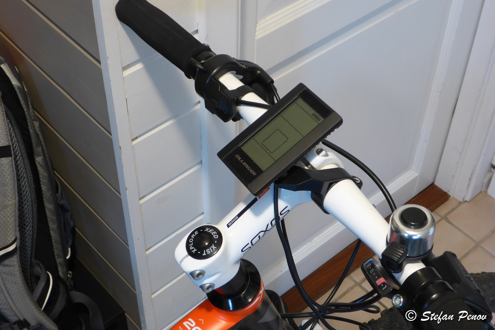
It looks solid and feels solid. The mounting is good and keeps it in the center. Later I used it to mount my new head light. It is 2 LED beast for off-road use but I like to see where I am going. 🙂 Having this LCD meant I won’t have place for the old bicycle computer anymore. This one doesn’t measure temperature and has no clock, but I can live with that (I hope). It shows current speed, average speed, max speed, trip distance, total distance, timer, pedal assist level, break state and battery level. Its model is C965. It also has a nice backlight if you want to see something in the dark. It doesn’t measure power, which would have been useful though.

On the left you see the control buttons and the throttle. There are three buttons: +, – and power. Enough to operate everything. If you read the manual, you will find, it shows you how to turn on the backlight and also how to activate the walk assist mode. In this mode the bike is moving at up to 6km/h, while you are holding a button. When you release it, it stops. The throttle is magnetic, so no issues with potentiometers and dust and water. It works good enough, but isn’t very linear. The response also depends on controller configuration for which a connection to a computer is required as well as a special software (more for that in another post). It was programmed to work only in pedal assist modes above mode 0, which means no throttle without pedal assist being active. Mode 0 turns off the pedal assist, but keeps the controller active and the LCD running, motor is stopped. I changed that from that software, so now I can use the throttle always and it is limited to half power (this is also configurable in software).
I didn’t have enough space on the right for the throttle and that is why I put it on the left. Also too much controls at one side is difficult to operate. Since it’s made for right hand, it must be operated above the handlebar when put on the left side. This is not very convenient and also isn’t quite safe. Your thumbs should be below the handlebar for secure grip. Because of that I bought another one, which is made for left hand operation.

It arrived a few days ago and now it is finally mounted. It is more comfortable. It has longer travel which means smoother operation. The control buttons are also closer to my hand. They were a little too far before.
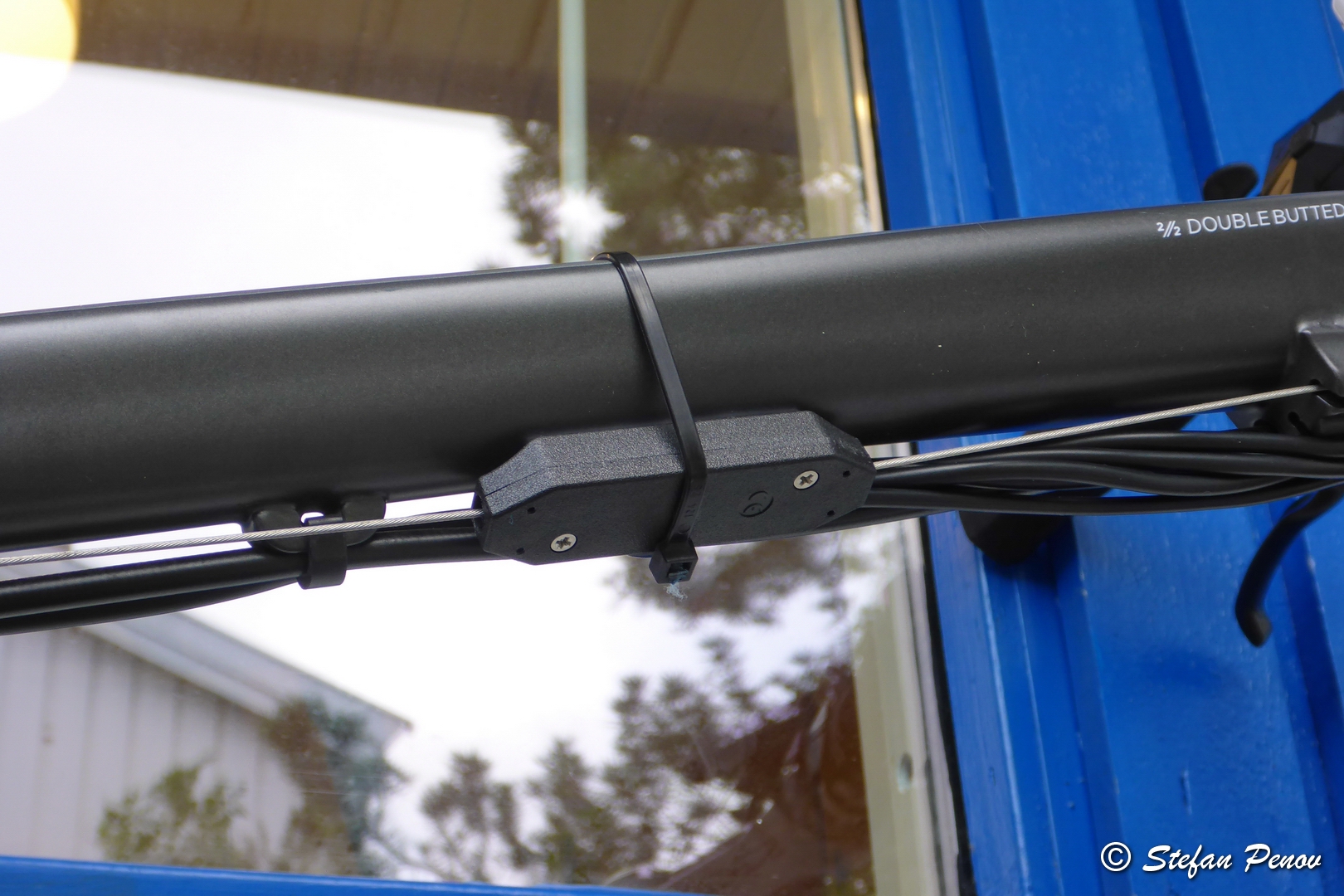
What you see on this photo is separately ordered gear sensor. What does it do? It simply acts as an e-brake and cuts the power to the motor during gear change to prevent damage to the gears if they are changed under load. It is expensive but does a good job. The gear cable goes through this sensor and rotates a small wheel with magnet. A hall sensor detects that and the motor is stopped. I hope there is some microcontroller inside, otherwise if it is just a hall sensor then it is extremely overpriced.
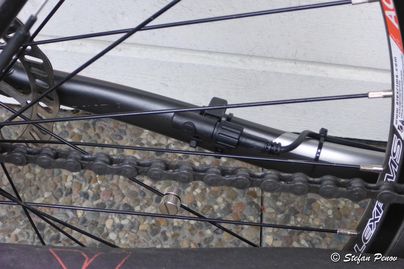
This is the speed sensor. You can also see the magnet on on spoke. There is a red 3mm LED on the back, which is on when the controller is working. If you move back it turns off. Not powerful enough to be used as a tail light. Since this is limiting the speed of the system some people set the wheel size to 16″ (the smallest available) in order to reach high speed. This might lead to dead motor because of overload. The limit is around 40-45km/h at 26″ which is more than enough.

Last but not least the e-brakes. This is something you better have. Otherwise you will have problem stopping. The motor stops a second or two after you stop pedaling but you might need to stop faster in some situations. That’s where e-brakes come in place. Unfortunately, those supplied with the kit are for cable braking systems and I use hydraulic. Since there was no option to choose, I just got the regular levers which were useless for me. Well, almost. I took the magnet off one of those e-brake levers and glued it to a moving part on my hydraulic lever (rear brake). The hall sensor I had to put in a heat shrink to make it water resistant and also glue it to the lever, but on non moving part. It took me some time to find the best positions, so the brake actually works and stops the motor. I used only one sensor because there are two connectors and the other one is used by the gear sensor.

This another view of my e-brake mod. It is virtually invisible as it is on the bottom of the lever and is black like it and like most of the cables and hoses.
When I finished building the bike, I couldn’t go to bed and not try it, even though I was very tired and it was past midnight. I went around the streets in the neighborhood without lights and at one point I decided to test the speed, so I was riding with 40+ km/h in the dark without lights. That was a little scary. 🙂 Don’t do this kids! There were no people walking or cars driving and I live on a very quiet street, so that is why I did it.

Let me show you again the finished e-bike (without the front mudguard and the new lights). One more change from the original you might spot. No? I will tell you then. It is the front disc. The rear one is also to be changed because it is making some grinding noise which I don’t like at all. Now the front is 185mm (AVID standard). 160mm was not enough for my taste (I am used to more aggressive mountain biking, not DH). Also those Tektro brakes are far from the most powerful hydraulic brakes I’ve seen. Adding the fact that the bike is almost 23kg, you better have good brakes in case you need to stop fast. Since I mentioned the weight with the kit mounted, let me tell you it was 15,5kg before that. It is heavy, but that’s where the motor comes in action. On flat roads it’s hard to feel the additional weight. Only during acceleration with the motor not running. I like to cycle, so I don’t really use the motor on flat roads. Mostly uphill. That is how I squeezed 90+ kilometers in one charge of the battery (13S4P, Samsung cells, 2950mAh each).
You might ask, what did it cost me to make it happen? Roughly NOK10500 (EUR1000) and it is worth it. That’s about the price of my 16 years old car which I sold before moving to Norway. Now I don’t really need a car. If I need one, I can rent it. No kids or other reason to have a car, so the e-bike is great substitute. Not very nice in rainy days, but a decent exercise and with the electric motor I can go faster uphill without sweating like a pig. That’s all I needed.
Next post will follow after some time and it will be about the software used for tuning of Bafang’s controllers. I am currently rewriting it, but it will take me some time. Why do I do that? Because I can. 😉

Thank you for ‘tuning’ the software. Good job. All the best. (found you via electricbike-blog Cheers)
You’re build notes very helpful! i want nothing more than to understand the build from A to Z, starting only by a choice of a strong frame and 2 rims. It’s so awesome to verify and double check my progress according to your comments! Thanks again!
Hi! Very inspirational reading about your build. I have a Giant Anthem 3 (2014), a soft tail with a 86.5 mm bottom bracket (pressfit PF41). I’m just trying to wrap my head around all the things I need to get. It’s not so easy when no one has the instructions for that exact bike. I will try and document my build like you did. Now I have to find the best supplier…. which is a jungle. Thinking em3ev.com might be a good place for ordering. Any pre-build tips? 🙂
The most important advice would be to make sure the motor will fit your bottom bracket if it is same type as mine and not hub motor. Other than that you should look for the features you want like power, configurability of the system, principle of operation (for example torque based motor power control). Last but not least is good supplier, whom you can contact about issues and service. You can get a kit cheap directly from China, but then you better forget about warranty unless it is a serious international chain for bike parts for example.
Hej. Har problem med att koppla in min Bafang BBS02 motor för omprogrammering. Får felmeddelande “error opening serial port”. (Har laddat ner programmet från din sida.)Hittar ingen vettig lösning nånstans….vet du nått bra tips? Vh Stefan
Hi! Had to use Google Translate. My Norwegian is very basic. You get this error because the serial port you chose is either locked by other program or the USB to Serial adapter has some issue that prevents it from being properly recognized by Windows. Driver issue is also possible.
Hi I’m an ebike rider and wondering where did you get all the information about the controller and it’s commands?
My bike broke down last week and I’m investigating in the electronic now, and why my display is not communicating with the controller. I will test your software to see if the controller is running. Do you know also what the different error codes mean, e.g. 30 ?
My motor does not have any hall signals, probably only speed sensors. Do they needs power supply? Where did you buy your kit?
Best regards
Thomas Keusch
Hi, Thomas. I found the information with a lot of Google searching and reading. As I mentioned somewhere in the articles about my bike, I also found the original configuration tool that Bafang uses ans it was packed with the source code. I have been programming with that same language (Delphi Pascal) for years, so it wasn’t a problem to make a better version. It took me a lot of time to understand the code, because of the Chinese comments and lack of any other documentation.
This tool of mine is meant for BBSxx series only. If you have different type, it won’t work and might cause even more trouble. Error codes you see on the display are different than the error codes in the PC software. Look for some manual for that LCD you have. It should have some error codes explained.
I bought my BBS02 from Dillenger, UK. BBSxx drives have speed sensor with a magnet (it has power supply through the cable and LED at the back for some reason) and crank rotation sensor (hall sensor that detects when you start pedaling). Both of those must be operational or you will see errors on the display or pedal assist will not work.
Hi I agree with your comment on the motor mount infact I would be a bit ruder. I have fitted a similar kit to an old Moulton APB. this gave me the opportunity to correct the motor locking plate by incorporating the rear suspension pivot bolt effectively providing a torque arm. Friction is no way to hold a motor in place!
I don’t seem to be able to post a picture but basically I fashioned a new locking plate which extended rearwards to catch another bolt. a similar solution would be to add a straight bar to one of the motor lugs and attach it to your frame using a clamp, it should be possible to find one that is made to hold a pump or bottle to a non lugged frame
Yes, the original mouting is not the best option. They should have made some sort of attachment for the tube above the motor.