 Nowadays energy efficacy becomes more and more important because of the increasing use of electricity in almost any aspect of our everyday life. We can’t even imagine what our life would be without electricity. As we all depend on the presence of electricity and the consumption rises, we must look for ways to use it more effectively. One of the reasons is that the electricity is generated using not so environmentally friendly technologies (like burning coals for example) so more use means more pollution. The so called “green” technologies become preferred now and even fashionable. “Green” stands for, but is not limited to: high effectiveness, low energy consumption, lack of pollution, avoiding the use of toxic materials in the manufacturing process, recycling materials.
The lighting problem

Lighting represents one of the biggest energy consumers in global meaning. For example lighting accounts for 22% of electricity use in America. Also America uses 25% of the globally produced electricity. With the current policies the global lighting energy consumption is projected to rise almost twice up to 4500TWh in the next 20 years. For the EU one of the latest summaries shows 743.39TWh electricity usage in the residential sector 12.8% of which is lighting. Increasing the efficacy of light sources can reduce significantly the amount of energy they use and the amount of greenhouse gas emissions produced by power plants. The number of companies developing “green” electronic devices increases. One of the most ambitious attempts to reduce the energy consumption of light sources is phasing out incandescent light bulbs. Many countries all over the world are taking measures to encourage the usage of more energy efficient lighting alternatives such as CFLs (Compact Fluorescent Lamps) and LED lamps. The first country which banned the sale and import of incandescent lamps in 2005, exchanging them for CFLs is Cuba. EU started phasing out the incandescent bulbs and plans to finish that in 2012. Some countries put an efficacy limit (lm/W) for the bulbs. USA also put some limits for the efficacy of light sources, which will be increased in the next 5 years so more low efficient lamps will be banned.
Replacing the incandescent bulbs with alternative light sources


Phasing out incandescent bulbs means they must be replaced with alternative light sources. There are no many alternatives so far. One can choose between the most common fluorescent lamps or CFLs and LEDs. The differences between the first two are not much. Standard fluorescent lamps are big and not very comfortable to install. Still most of them use starter and ballast but electronic starters can be found on the market too. CFLs use electronic circuit to operate. Both has high efficacy (~22%) which is about 2÷3 times higher compared to the incandescent bulbs (10%). CFLs are offered in variety of forms and sizes as well as mounting sockets. CFLs can be easily used to replace incandescent bulbs. The major problem with all fluorescent lamps is that they can’t be used for applications requiring frequent on and off switching. This will cause them to age rapidly and their lifespan may become much shorter than that of an incandescent bulb. The average lifespan during normal operation of fluorescent lamp is from 10 to 20 times longer compared to incandescent one. Incandescent lamps have a lifespan of 750÷1000 hours whereas fluorescent lamps have lifespan between 6000÷15000 hours. Another disadvantage is the UV light emitting which is harmful for the human eye. All the light created inside the lamp is in the UV spectrum (predominantly at wavelengths 253.7nm and 185nm). The fluorescent phosphor converts the UV light into visible light. The UV emission is extremely low when the lamp is new but increases through time as the fluorescent coating ages. These days fluorescent lamps contain as much mercury as the lamp needs for its lifecycle so it can not emit dangerous amount of UV light. Another disadvantage is that dimming fluorescent lamps is harder than dimming incandescent one. It is difficult to find dimmers for this type of lamps and they are more expensive. There are even more disadvantages coming with the fluorescent lamps like low power factor, limit of operation temperature (they operate best at room temperature), noise coming from ballast with minor fault, light flicker at the mains frequency which is not visible but can cause headache and last but not least the environmental issue about disposal of the phosphor and the toxic mercury form the fluorescent lamps. As one can clearly see fluorescent lamps and even CFLs are far from perfect and in some cases are worse choice than incandescent bulbs even though they are more energy efficient. Solid-State Lighting (SSL) may soon become solution to this problem as Power LED prices drop and their lm/W ratio increases.
The “LED Era” of lighting

 Solid-state lighting is may be the most significant development in lighting since the invention of electric light almost a century ago. It offers unprecedented freedom in terms of colors, dynamics, miniaturization, architectural integration and energy efficiency. Actually it is the first step in lighting technology moving ahead from vacuum-based solutions. Rudy Provoost, CEO of Philips Lighting, believes that LEDs will shape the future of lighting, adding that switching from older incandescent and mercury vapour lamps to LED or solid state lighting products can reduce energy consumption by 10 percent. “With additional improvements such as sensors and lighting controls, the total savings could go up to 30 per cent annually,” he said. He added that despite the market for global LED lighting is still relatively small today, accounting for US$4 billion in revenue, it is expected to grow to US$30 billion in the next 15 years.
All these prognoses are great looking but why should we move to LED lighting and what makes it so universal and so desired? Near the end of the 19-th century Thomas Edison invented a revolutionary light source – the incandescent light bulb. At that time no one knew that his invention will become the most widely used light source on Earth. Now, the LEDs start their long way in the history of lighting. In the matter of fact the LED has been making its way for the last 35-40 years. But in the last few years more and more power LEDs become available to customers with higher efficiency so finally they can be used for lighting and not only for indication in various electronic devices. The main reason LEDs are preferred choice is their low power consumption. They are also considered extremely reliable. One reason is their ability to perform under high vibration stress and high impact forces.
Talking about low power consumption it must be mentioned that some of the recent requirements for incandescent lamps were given as 17lm/W whereas the most efficient LED to date is able to produce 100 lm while consuming 1W energy. This makes it about 6 times more efficient. Some of the very latest laboratory experiments have recorded 150 lm/W efficiency.
Another reason to move to LED lighting is the ability to use RGB LEDs and change their color in the way you like and as fast as you like. This creates a whole new marketing range. As the LEDs are quite small they can be mounted virtually anywhere. Light fixtures can be made of any shape and size. All these unique features make LEDs the light source of the future.
Nice example for innovative lighting is Light Blossom – a futuristic conceptual project by Philips Electronics. This “light flower” is daring look into the future showing the endless possibilities before LEDs. During daytime when the Sun shines, Light Blossom collects solar energy, changing its direction to “catch” as much sunlight as possible. When clouds hide the Sun Light Blossom changes its shape and tries to “catch” the wind and accumulate more energy. The high-tech flower stores energy for its own use but it can also feed it back into the grid. When the night falls, Light Blossom closes and transforms into smart light source, lighting up only where and when it is needed using proximity sensors. This saves energy, reduces “light pollution” and allows the passers-by to see the stars again.
Power LED – what makes it different from other LEDs?


As the working principle inside the semiconductor structure is the same for all types of LEDs it will not be described here. The main difference between low power LEDs and high power LEDs (≥1W) is in their construction. Low power LEDs’ forward current usually is limited to 20÷30mA maximum so the dissipated power is fairly low and the semiconductor die is cooled only by the leadframe. The die itself is also smaller in size because it emits less light and therefore heat. High power LEDs produce much more light energy and heat and the semiconductor die is larger so it can be cooled more easily. Despite that high power LEDs need forced cooling in order to function normally. This is achieved by adding thermal heatsink also known as thermal pad into LEDs’ body. Usually these LEDs are mounted on heatsinks with suitable size or special printed circuit boards so their junction temperature can be kept low enough for them to function normally.
Most power LEDs are designed in surface-mount (SMT) or chip-on-board packages. The heat flux at the thermal interface in SMT package can be in the range of 5÷20W/cm2. As all LEDs are semiconductors (AlInGap and InGaN) they have physical properties and limits similar to other semiconductor devices like transistors and ICs. While the heat of filament lights is being removed by infrared radiation, LEDs relay mostly on conductive heat transfer for effective cooling. Depending on power dissipation and light emission uniformity, the cooling method can be passive (heat sink in natural convection), active (fan-cooled heatsink) or liquid cooling. As power LEDs are very small in size, they are used in variety of applications, therefore their cooling systems must be designed with the ambient temperature and the specific end use in mind. The LEDs’ maximum allowable junction temperature is limited to around 120÷150°C (up to 185°C in recent developments) compared to 1500÷3000°C for incandescent lamp. Cooling is may be the biggest problem before power LEDs’ integration.
Contemporary Power LED technology


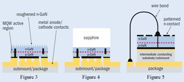
The most efficient power LED up to date is Luxeon Rebel by Philips Lumileds, recognized with technical innovation award at Lightfair 2009. It produces 100 lumens per watt at 350mA. This LED utilizes the same semiconductor materials as other white LEDs do (InGaN). It is produced by taking an flip-chip LED (FC LED) that has an anode and cathode on the same side and bonding it to a submount or package using gold interconnects (see Figure 4). An excimer laser removes the sapphire substrate before photo-electrical-chemical etching of the top GaN layer roughens the chip’s surface with an ultraviolet lamp and a dilute potassium hydroxide solution. This texturing disrupts wave-guiding in the high refractive index epitaxial layers, increases light output and dramatically boosts the LED’s external quantum efficiency. The TFFC LED (Thin-Film-Flip-Chip) architecture (see Figure 3) produces excellent device characteristics. This design was proposed more than a decade ago and has been implemented recently by several chip manufacturers. One can compare TFFC structure to vertically injected thin-film (VTF) structure (Figure 5) and see that VTF’s patterned n-contact reduces the chip’s effective emitting area and the wire bond obstructs light emission.


The other major drawback of VTF is that the intermediate substrate increases the thermal resistance of the package. The VTF based LED arrays (see Figure 6) suffer from another problem caused by bond wires. There are many wires in the array and they block significant amount of light and force the primary optics used in projection displays and illumination systems away from the emitting surface of the LED. The light loss is eliminated with TFFC LEDs (see Figure 7) and this also helps to reduce the distance to the primary optics.
Laboratory tests comparing TFFC with FC and VTF blue light emitting LED chips, produced from the same GaN-on-sapfire epiwafers show that TFFC structure produces the highest output (see Figure 8). At 1 ampere drive current, the output of TFFC is 46% higher than that of the FC device and 17% higher than that of the VTF chip.
Like the fluorescent lamps which emit UV light converted into white light by the luminescent phosphor, white LEDs use the same principle. Some of the first white LEDs used three semiconductor dies (one for each primary color) in order to produce white light. Today’s white LEDs are actually blue ones, whose semiconductor die is covered with phosphor layer. This layer converts the wavelength so the resultant color is white. Depending on the density of this layer different color temperatures can be achieved. The quality of the color rendering is a major requirement for LEDs which will be used in standardized light applications. That is why all white power LED manufacturers are optimizing their technologies not only for high efficiency but also for high CRI (Color Rendering Index). This index represents the ability of light source to reproduce the colors of various objects faithfully in comparison with an ideal or natural light source. Higher CRI means better color representation. High CRI light sources are required in color-critical applications such as photography and cinematography.

The LED chip described above is only part of the final product. Figure 9 reveals the structure of Philips Lumileds’ Luxeon Rebel white LED. The LED chip is mounted on a metal interconnect layer through the bond layer. The interconnect layer is used to connect LED’s anode and cathode to the terminal leads on the bottom of the LED. Both leads are electrically isolated from the thermal pad by a ceramic substrate. The thermal pad has to be mounted on specifically designed PCB so the LED can be cooled efficiently. A silicone lens is mounted on top of all other components.

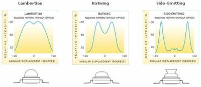
Some Power LEDs are manufactured with different types of lenses so they have different radiation patterns, required for some special applications. The radiation pattern describes the relative strength of the light in various directions from the light source. The variety of radiation patterns gives lighting designers more flexibility in controlling the light in their application. Example patterns and the corresponding graphic representations are shown at figure 10.
Power LED lifetime analysis


The high reliability of LEDs has already been mentioned in this article. The long lifetime of LEDs is actually one of the main reasons they will most likely become preferred light source in the near future. Incandescent light sources don’t show significant changes in their light output until they fail and become totally unusable. LED light sources do not tend to fail that way. Instead, the light output degrades gradually over time. The operating life of a power LED is very long, and often longer than that of the product in which it is embedded.
The light sources are being rated in terms of the time by which a certain percentage of the light sources is expected to have failed. For example B10 value denotes the time by which 10% of the light sources are expected to fail. Often used is the B50 value representing 50% failure rate, also called average rated life. New major property used only for LED light sources is also being rated. It is rare for LED to fail completely so its “lumen maintenance” is being rated. Because many applications require specific light output, designers need to know the expected lumen maintenance period. A power LED industry group, the Alliance for Solid-State Illumination Systems and Technologies (ASSIST), found that 70% lumen maintenance is close to the threshold at which the human eye can detect a reduction in light output. The ASSIST research shows a 30% reduction in light output is acceptable to the majority of users for general lighting applications. ASSIST proposed two ratings for lumen maintenance: L70 (the time to 70% lumen maintenance) and L50 (the time to 50% lumen maintenance). Factors like forward current and junction temperature also affect the useful lifetime of a LED. Higher temperature and/or forward current mean shorter lifetime of a LED. Figure 11 represents the lifetime of Luxeon K2 power LED across current and temperature variables and B50, L70 ratings. Comparison between Luxeon LEDs and conventional light sources showing the light output degradation through time is shown at figure 12.
Power LED drivers


As the forward current of power LEDs has to be limited, the need of special LED driver is obvious. The well known spot lights use mostly 12V power sources. These sources are conventional or electronic transformers. They are constant voltage sources and respectively they do not produce constant current. That is the reason they can not be used in LED lighting applications. LEDs must be powered through constant current source. The LED drivers available today are in fact constant current sources. They consist of some type of switching mode power supply (mostly step-down) and constant current generator. Some drivers have embedded current generator so they use less external components. One of the most simple power LED driver circuits is shown on the schematic at figure 13. ZXLD1360 produced by Zetex Semiconductors requires just a few external components which makes development of miniature PCBs very easy. This also saves time to lighting designers. RS in the schematic is current sensor used to set the constant current flowing through the LEDs. L1 and D1 are part of the step-down converter. C1 is filter capacitor for the power supply. This driver is capable of driving LEDs with currents up to 1A using the internal NDMOS switching transistor. The driver can also be controlled for dimming purposes using DC voltage control or PWM signal. The total efficiency of the driver circuit (excluding LEDs and power supply unit) can be tuned up to 95%.
ZXLD1360 is low voltage driver so it needs additional power supply source. Some manufacturers have developed LED drivers which use the mains grid directly as power source. Such driver is LM3445 by National Semiconductor. The application circuit (see Figure 14) suggested in the datasheet has the capability to control the light intensity using conventional triac dimmer. This schematic contains a lot more external components but it does not require additional power supply unit. Its efficiency is in the range of 85÷90% depending on the number of LEDs connected to it. As in this case the power source is the mains grid there is no additional power losses like in the previous driver circuit. On the other hand the driver’s efficiency decreases with increasing the mains grid voltage (using the driver with 220V instead of using it with 110V mains grid).
Power LED application


Power LED technology is still expensive as well as all power LED lamps. This is in fact the main reason for which solid state lighting is still used mostly for architectural lighting and special applications (industrial for example). Despite that there are plenty of LED lamps and LED drivers on the market. Some good examples are E27 MASTER LED lamp by Philips Electronics and MR16 LED spotlight using Cree X-Lamp LED.


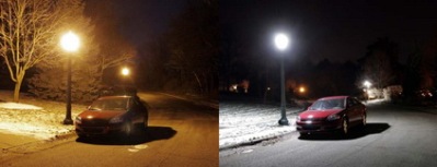
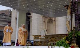
Power LED light sources have already found their place in variety of applications like street lighting, architectural lighting, office and interior lighting, dental and medical applications and even in the Vatican Mobile Podium.

References
- Paul Waide (Senior Policy Analyst Energy Efficiency and Environment Division International Energy Agency), 2006 “Meeting demand for energyservices through increased energy efficiency: potentials and policies”
- Paolo Bertoldi and Bogdan Atanasiu (European Commission – DG Joint Research Centre, Institute for Environment and Sustainability) “Residential Lighting Consumption and Saving Potential in the Enlarged EU”
- “Phase-out of incandescent light bulbs” – http://en.wikipedia.org/wiki/Phase-out_of_incandescent_light_bulbs
- “Fluorescent lamp” – http://en.wikipedia.org/wiki/Fluorescent_lamp
- “Compact fluorescent lamp” – http://en.wikipedia.org/wiki/Compact_fluorescent_lamp
- “How to be Sure That LEDs Are The Future of Global Lighting” – http://www.ehow.com/how_4930073_leds-future-of-global-lighting.html
- “Light-emitting diode” – http://en.wikipedia.org/wiki/Light-emitting_diode
- Norbert Engelberts (Advanced Thermal Solutions – Norwood, MA), 2008 – “Cooling high-power LEDs” (http://www2.electronicproducts.com/Cooling_high-power_LEDs-article-farr_ats_may2008-html.aspx)
- Oleg Shchekin (staff scientist at Philips Lumileds Advanced Laboratories), Decai Sun (section manager in the R&D department of Philips Lumileds), 2007 “Evolutionary new chip design targets lighting systems”, Compound Semiconductor vol. 13 num. 2
- “Understanding power LED lifetime analysis” – Philips Lumileds’ Technology white paper
