
Furniture manufacturer IKEA hardly makes any TV tables, capable of accommodating large audio-video equipment for home theater systems. On top of that the few available models haven’t been designed with cooling in mind so they have no opening on the back to let the hot air out. This might easily result in overheating of expensive equipment. I decided to solve this issue with my home theater system by designing automatic cooling device. It has two zones of operation for which temperature limits can be set separately. It uses two digital temperature sensors and two PWM controller cooling fans.
This first part of the project will be about the hardware I chose and the PCB design.

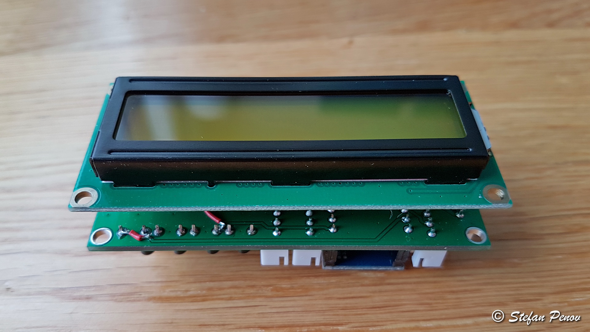
My TV table is separated in three zones, two of which I filled up with things like PlayStation, AV receiver, disc player, NAS, Internet modem. All those create heat during operation and some of them become quite hot. This is the reason I decided to design my automatic cooling device to operate in two separate zones. I wanted to make something fairly small and simple to use. I had one 16×2 character LCD (standard HD44780 type) and thought it can be of use for that project. I based the PCB design around that display as you can see in the photo. Let’s see what else I had available.

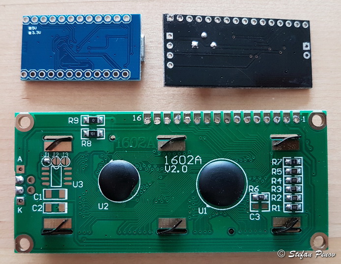
The small board at the top left corner is Arduino Pro Micro. It is not a standard Arduino design. It is based on two different Arduino models, combining small footprint with a lot of microcontroller resources. It is easy to find on eBay and is quite cheap. The darker board at the top right corner is I2C to parallel converter for easy control of character LCDs all the way to 4×20 size. Using this converter you don’t need to use many microcontroller pins for communication with the display. There are Arduino libraries available for serial LCD control that work well with this one.
I had to choose what kind of temperature sensor and cooling fans to use. I wanted to make things simple, but good quality so I chose Dallas DS1820 digital temperature sensor and 4-pin PC case PWM controlled fans from Arctic Cooling. The sensor is very accurate and with high resolution. This will allow for finer adjustment of the cooling fans’ speed. There are Arduino libraries and sample code available for DS1820, which again simplifies the design. The cooling fans I chose have a long history and Arctic Cooling has improved them over time. I have used them for my PC in the past and was very pleased with their extremely low noise level.
Let’s have a look at the schematic. It is quite simple actually.
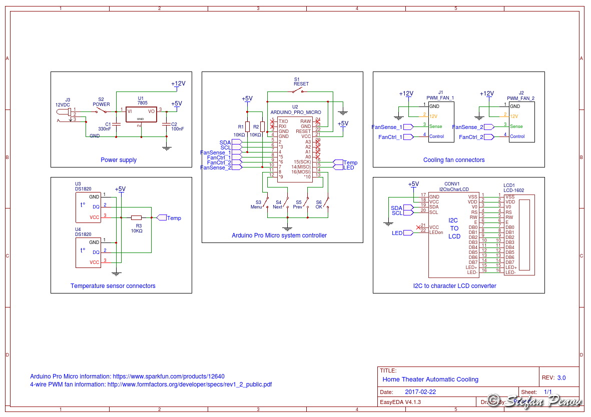
There is 7805 linear regulator to supply the Arduino, LCD and sensors from the 12V power supply. The fans operate at 12V, so they are connected directly. DS1820 can operate on a single line and that is what you see in the schematic. They have unique IDs that separate them when temperature readings are taken. The pull-up resistor is standard for I2C communication.
The I2C to parallel converter board is connected directly to the display without additional components. It also has the option to control the backlight through transistor, so a microcontroller digital IO pin can be directly used for that purpose.
Around the Arduino there are a few control buttons (including reset) and a couple pull-up resistors for the PWM fan outputs, which provide pulses for speed measurement.
The PCB design was focused around the LCD, because I wanted to keep the front as small as possible. This is how it looks:
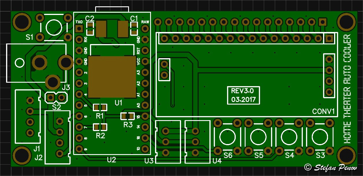
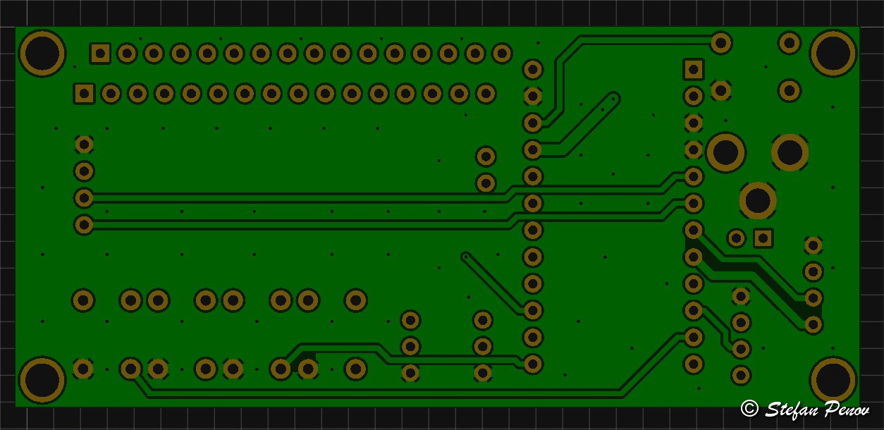
It is the same size as the LCD PCB and has mounting holes at the same place. Those will be used later when I design plastic enclosure and 3D-print it. There is nothing really interesting about this board. The only thing worth mentioning is the connectors for the PWM fans. I wanted reliable connectors that will not disconnect with a slight pull of the cables. I decided to replace the original connectors of those fans with JST XH connectors.
There is one more thing that I want to mention here. The tool I used for my schematic and PCB design. Surprisingly, it is a completely free online based tool with excellent capabilities for any hobby project as well as for professional ones. This tool is called EasyEDA. It is completely online based and works through a web browser. Unlike most free PCB design tools and free versions of professional tools, the only limitation with Easy EDA is 6 layers. You can use as many components as you wish and design a huge PCB if you want. If that is not enough, there is also simple spice simulator and auto-routing features. You can import variety of popular schematic and PCB file formats for reuse. There is export function, which unfortunately does not export back in all those formats yet. The database provides large number of schematic symbols and PCB footprints. Users can design their own as well (those will be public). I have Electronics engineering as profession and have been working in that field for the last 8 years. I have used OrCAD and Altium designer in my work and a few other tools like Eagle for hobby. None of the free alternatives seems to be even close to what EasyEDA offers. It can’t compete with the professional tool, no doubt. It is not targeted at professionals anyway. It can be used for prototyping and hobby. In that area it is unbeatable in my opinion. Especially the fact it is a free tool, unlike the professional ones, which cost a few thousand EURO.
Let me show you this project in EasyEDA’s website
Users can have multiple projects and create pages like the one you just saw. They can even have discussions below the project. If you click one of the “Open in Editor” buttons on the project page in EasyEDA, you will be redirected to the actual schematic and PCB editor. You can also click here to go to the editor. Even unregistered users can play with the editor, but they can’t save any changes.
You are probably interested at this point, but let me tell you about one more thing. When you finish the design of your PCB, you can prepare it for manufacturing by generating gerber files (downloadable for your convenience) and you can actually order your PCBs through the same system. Minimum order is 5 PCBs and you can get a few thousand if you want. You can even import gerber files you created with another tool and order PCB with EasyEDA. This makes it real all-in-one tool.
Here are the PCBs I got produced by the factory:
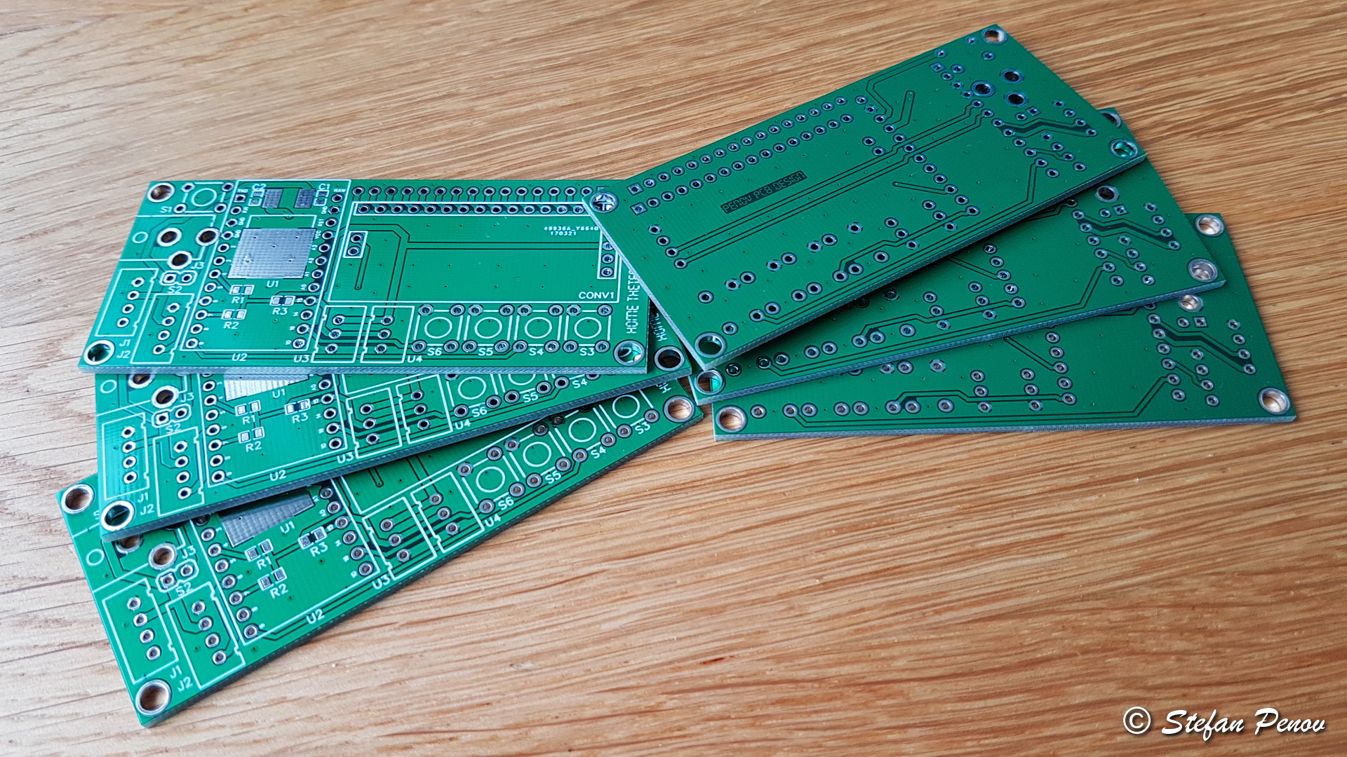
They are actually six, because of the minimum area needed for manufacturing. This costs less than USD20, shipping included. The quality of the PCBs is great and the only imperfection I have seen is that the silkscreen is not always excellent, but nothing to worry about. This is in fact much better quality than other services I have used at very similar price. I am very pleased with the result.
Here is the assembled board:

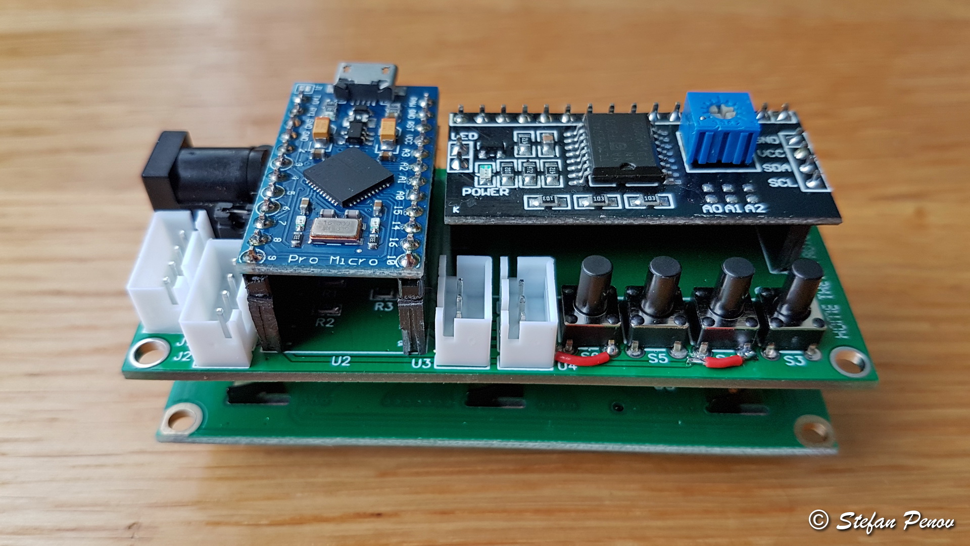
I know, the buttons are too short to be reached from outside the box I will be designing. I will make extensions and in future I will use low profile headers for the modules I put on the main PCB.
The next step for my project will be designing a firmware for the Arduino board, which I will complete as soon as I have enough time. After that I will design the plastic enclosure and mount the finished device on my TV table.

WELL DONE! Exactly what I am looking for! Will this version (when firmware is ready) work from hard-coded preset temperature threshold with associated RPMs or will one be able to set/reset those in real-time? I’d love this to be displayed remotely in a browser (I’ve seen pages hosted on an SD card?), but that implies an Ethernet connection to control it all and THAT is beyond me! Any guidance? BTW: you have extra boards. Would you consider assembling a second one and selling it – for a profit of course?
I plan to make changing the temperatures possible using the buttons on the back. I don’t havy any plans to make this an IoT device. Not many pins left for connecting to ethernet module. Not impossible of course. I intend to release the full source for this project so you could modify it for your needs. Unfortunately I am occupied by other things and haven’t done the programming yet.
I do have 5 more PCBs. I could send you one, but I do not have all thr components needed for it available. I ordered many of those on eBay and it takes about a month to gather them all. I belive there is full BOM available so you can get the components and assemble the PCB yourself. It is not very complex or difficult. My PCBs have a small mistake which needs to be corrected, but the project on EasyEDA has been fixed. I am not sure about that, but I think it might be cheaper to order 5 PCBs directly through EasyEDA than shipping from Norway.
I am sorry if that is disappointing for you. I am still willing to help you get the module assembled on your own if you want to do it. That is of course if you are good with SMD soldering. It is easier than it seems actually. All you need is a set of small tweezers and soldering iron with a sharp tip.